A New Control Method for Three Phase Rectifiers with Sinusoidal Input Currents (Extended abstract)
The new EMC norm EN61000-3 stipulates strict limits for current harmonics. Electronic equipment with uncontrolled mains rectifiers cause high level harmonics of lower orders in the mains. However, the generation of harmonics can almost completely be avoided by using controlled rectifiers with sinusoidal input currents. Unfortunately, the control unit of this type of controlled rectifier is expensive. Conventional control methods base either on the nested loop control, or on digital or analog real-time pulse pattern processing. The aim of this paper is the presentation of a simplified control method for rectifiers with sinusoidal input currents.
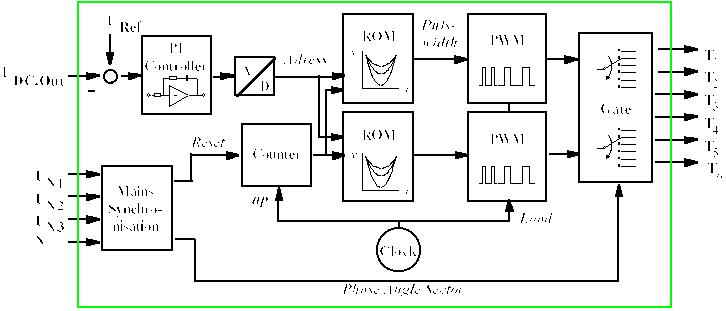
Due to the periodicity of the mains voltages the required pulse patterns for control are predictable and of finite size. Therefore it is sufficient to pre-process the pulse patterns just once e. g. with the help of a PC. The results are stored in a ROM. The only task that remains for the control unit is to ensure the periodic output of the stored patterns synchronised with the mains voltages. It is possible to store several tables of pulse patterns, computed for various power levels, in order to be able to function at various operation states. If a decrease of the output voltage is detected the control unit reacts by selecting a pattern for a higher power level, and vice versa. In this way a stable output voltage can be achieved, for instance.
The suggested control method is very cost effective. No measurement of the mains voltages and mains currents is required. The solution is digital but no computing power is necessary in the control circuit. The proposed control method can be adapted to all single and three phase rectifier topologies.
This paper presents experimental results of two three phase rectifier topologies based on boost converters working in continuous conduction mode. The first topology comprises three single boost converter stages that feed a common dc voltage link. The second topology is a fully controlled six-pulse bridge.

| Fig. 1: | Control unit of a six-pulse bridge for achieving sinusoidal input currents and a controlled dc output voltage |


